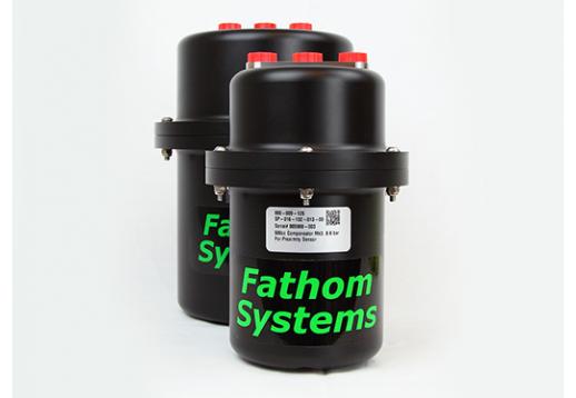
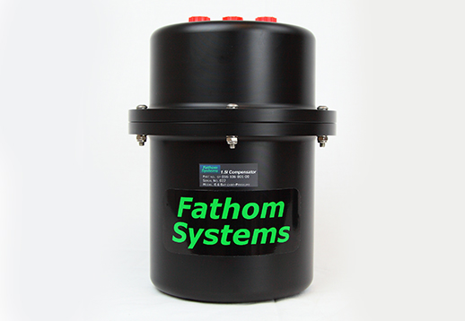
Hydraulic Pressure Compensators
Fathom Systems offer hard bodied diaphragm over-pressure compensators in sizes 500cc and 1500cc which may operate in an intelligent or non-intelligent mode.
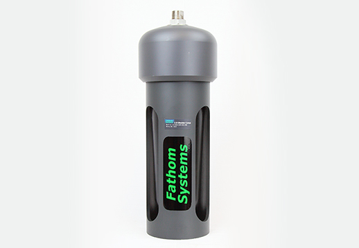
There are many options including supply with our without a low oil level proximity sensing or level sensing indicator, pressure relief valve, QD fill point as well as 3 different over-pressure ratings. These are field proven and used industry wide in both the commercial diving and ROV sectors. A 2300cc bladder compensator is also offered which is more commonly used in SAT diving applications to pressure compensate an oil filled junction box with an umbilical termination. For all options and sales enquiries, please complete Compensator Specification Sheet and send to: enquiries@fathomsystems.co.uk
Pressure Compensator Guidance Notes
Introduction:
The following notes are provided for information only, and no responsibility is taken for their application.
The notes mainly apply to compensators that use a spring (or springs) on the ambient pressure side of a diaphragm to provide a, generally, modest overpressure on the system side of the diaphragm. Other types of “compensator” that you may come across include bladder and “tyre” compensators. A bladder compensator is used where overpressure is not wanted but some flexible volume is needed. A typical application for a bladder compensator would be to pressure equalise a junction box that has non or poorly water blocked cables glanded into it. An overpressure compensator would drive fluid up the cables and quickly exhaust itself.
Tyre compensators do provide overpressure but in a non-linear fashion and tend to be big and heavy - but they are very cheap!
A final variation on the overpressure compensator is where weights (rather than springs) provide the force for overpressure. Although simple (and they can provide constant pressure throughout the range of diaphragm movement) this arrangement only works when the compensator is the right way up and by definition its heavy!
The first section of this document describes the main applications for pressure compensators (if you can think of any others let me know!).
The second section describes how to approach the most common calculations needed to properly specify a compensator.
The third section details how to distinguish a good from a not so good compensator.
Fathom Systems has a great deal of experience in the application of pressure compensators for numerous applications. More detailed technical assistance can be obtained from FSL, if required
Compensator Applications:
Pressure Balancing (Compensation)
Where void spaces are to be fluid filled and pressure compensated against elevated external ambient pressure. In this instance the overpressure requirement of the compensator is usually low.
Volume Change & Over Pressure Protection
Where, the fluid volume of an ambient pressure system varies, the variable volume of the compensator is used to cater for this. Volume changes may arise, for example, from temperature changes, pressure changes (like everything else fluids are compressed by elevated pressure), trapped air, stroking a hydraulic cylinder or the need to transfer fluid from one system to another.
Where volume change in a system might cause over-pressurisation the compensator can be used to maintain set pressures without venting system fluid overboard. Of course systems will still need relief protection so that pressure is kept within safe limits even when the compensator reaches its mechanical stop at maximum volume.
Pressure Spike Suppression
In a hydraulic system pressure spikes in the return side can be generated by rapid changes in flow rate, through rapid valve closure or other shock loadings.
In the worst cases this can cause filters to bypass or even damage hydraulic components. Axial piston pumps, where the piston slippers are not positively restrained are particularly susceptible to this. If case pressure drops (even momentarily) below inlet pressure, the slippers lift off their pads and are then swiftly smashed back down when the pressure differential returns to normal. This reduces pump life to hours or even minutes!
The flexibility provided by a suitably located compensator can be used to damp down and minimise these spikes. Size of compensator is generally not relevant for this application but to be effective the compensator needs to be mounted as close to the component to be protected (generally a pump) as possible and large diameter but short pipe runs should be used. Finally the compensator MUST be at mid stroke. If it hard up against its stop – It won’t work
If you need to damp spikes on the pressure side you will need to use an accumulator rated to full system pressure. These are available, along with technical information for this application from either the big hydraulic component suppliers such as Rexroth or Parker or from the more specialist accumulator suppliers like Fawcett Christie
Pump Cavitation Prevention
One of the benefits of running hydraulics underwater is that, once the system is at depth, pump cavitation is not a problem. This is because the NPSH (Net Positive Suction Head, which is the difference between the static pressure at the pump inlet and the vapour pressure of the working fluid) increases with depth. Pumps cavitate (and are then damaged) when the NPSH drops to zero; generally because the pump is sucking too hard.
If the fluid’s vapour pressure is assumed to be zero, then the maximum NPSH available at the surface is 1 bar (atmospheric pressure), at 3000msw the available NPSH is 301 bar!
As an aside, this availability of enhanced suction pressure means that if the suction side of the circuit is blocked for any reason then the pump can generate very high negative pressure differentials. For example early Scorpios were known for their ability to “pressure form” Aluminium alloy valve pack lids around the valves inside before they ultimately imploded!
So, although pump suction pressure isn’t a problem when you are at depth it can be when you are running at the surface or in very shallow water.
All pump manufacturers specify how fast you can run their pumps and (if they are variable displacement) what the maximum displacement should be. To run at high speeds and/or high displacements they will then specify that a boost pump be fitted on the suction side to push up the NPSH and keep the system in the safe zone.
To save weight & complexity we generally don’t fit booster pumps to underwater systems but can supply the additional NPSH needed at the surface by means of a compensator. Pump manufacturer’s data can be used to calculate how much overpressure is needed to cater for the chosen operating conditions. As for spike protection the compensator should be mounted as close to the pump as possible and large diameter, short pipe runs should be used.
An extra benefit of adding pressure to the pump suction side is that it reduces the size & number of any air bubbles that may be pulled out of solution on the suction side of the pump. This also helps to improve pump life and reliability.
Calculations:
Fundamentally there are two choices to make when specifying a pressure compensator, which are:
- What should be its pressure rating?
- How big should it be, or rather what should its swept volume be?
Pressure Rating
The choice of pressure rating is largely defined by the requirement of the system to which it is attached. For example, only low pressure may be required to pressure balance a void space. Higher pressure may be needed for applications such as spike suppression or cavitation prevention at a pump suction inlet.
Specifying operating pressure requires some system analysis and detailed examination of supplier’s (such as pump manufacturers) information.
Swept Volume
Volume requirement is dictated by anticipated volume changes between extremes of working conditions. These volume variations can arise from one or more of the following conditions:
- Temperature fluctuations. System fluid volume will change as the system temperature changes. For example a typical mineral oil heated from 0oC to 50oC will expand in volume by nearly 3%.
- Pressure fluctuations. System fluid volume will change as the system pressure changes. For example a typical mineral oil pressurised from 1barg to 300barg (equivalent to 3000msw) will shrink in volume by nearly 2%. Pressure fluctuations may arise from elevated working pressure as well as increasing ambient pressure. In addition, elevated working pressure in the system will act to increase the volume of pressurised spaces such as piping and vessels. In turn these expansions will require additional oil to fill them.
- Variable volume components within the system. Hydraulic cylinders, for example, have different internal volumes depending whether they are in the extended or retracted condition.
- Trapped air. Any air that remains in the system will be compressed as ambient pressure increases.
All of the above potential sources of volume change should be calculated at the expected extreme operating conditions and the swept volume of the compensator sized accordingly.
The spreadsheet output, below, demonstrates the process by which the necessary volume for the compensator can be calculated.
Some of the inputs can be calculated accurately, others such as trapped air and variable pressurised have to be estimated/guessed!
(If you don’t want to tackle these calculations yourself, please come back. Very soon we will have a Java application on the site that will do these calculations for you.)
Good and not so good compensators
How can you tell if you are buying a good or a not so good compensator?
Of course there are the usual indicators:
- Does it look the part (well designed and made)?
- Are the materials suitable for the application?
- Are the compensator’s pressure rating & swept volume suitable for the application?
- Have you used them successfully (or not) in the past?
There are some other, more subtle, features that are worth noting. These mainly arise from how the designer has matched diameter of the diaphragm, swept length of the diaphragm and the spring that is used to provide overpressure. There are ways of doing this that will result in a more volume efficient design that has a flatter pressure curve than one that has been designed using guesswork!
For compensators of similar swept volume, it is surprising how different they can be in size. Rather than clutter my ROV with wasted space I would always go for the smaller design.
When compensators are used to provide overpressure it can be argued that the ideal situation would be one where the compensator provides constant pressure between its full and empty positions. This is impossible when a spring is used to provide the overpressure force and luckily constant pressure is not usually necessary.
Again it is surprising how many manufacturers manage to supply compensators that have healthy overpressure when full, but next to nothing when nearly empty, so it is worth checking that the amount of overpressure available from the compensator is suitable for the application throughout its working range; from full right through to empty.